Dimensioning the Filler Boards

These pieces are still not glued into place, but the mock-up now shows the actual pieces that I intend to install.

In order to make sure my filler boards would fit properly and release properly from the aft section of the footwell, it was important that I make the actual boards, cut to their actual widths and lengths.

(Floor held back to better show the filler board arrangement)

IMG_1990
The depth below the cockpit sole is just under 7″ in the aft section (the hull slopes upward on the aft end).  By making the filler boards 6,3/4″ wide they fit perfectly.  There’s actually room for an additional cooking kit board to fit in this area if desired.

Here are the 6 filler boards.  They measure 26,3/8″ x 6,3/4″ x 3/4″.  I made them from regular pine purchased from Home Depot.  I rounded the corners and drilled a 1,1/4″ hole in the center for one-handed loading and unloading of the boards.  If you lay the boards across the seat tops, they will fill the gap from bulkhead #4 to the fore edge of the lazarette, minus 19,1/2″.  The final 19,1/2″ will be filled using the footwell grate (not yet build).

IMG_1991

The side panel supporting the beam also acts to fill this area to minimize the flood-able area.  These side panels could even be widened a bit more if desired.  The side panels measure 3/4″ and were convenient to build by gluing up (2) 3/8″ scrap pieces.

IMG_1989

The centered cleat on the hull serves two functions:  1-it prevents the filler boards from spilling forward and 2-it prevents the footwell floor grate from sliding aft.  The bottom of the footwell (inside all cleating) measures 19,1/2″ x 26,1/2″.  As stated before, the 26,1/2″ spacing works seamlessly (fingers crossed) with the seat top spacing, making the footwell grate compatible in both locations.

So much to get right here–I’m taking my time, working slowly and deliberately   

Fireplace Onboard Scamp

I love a wood burning fire.  I love the look, the smell and the soul warming heat.  But, we don’t always have room for a wood burning stove.  Sometimes we’re in a small nylon tent, a small sailboat or even a snow cave.  When these situations arise, what do you use for heat?

IMG_1983

I love all 3 of the above items for slightly different reasons.  Let’s discuss the good, the bad and the ugly:

Let’s start by describing both ends of the spectrum:

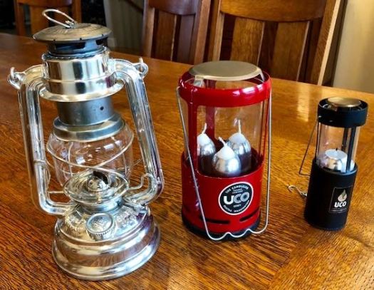
First Up:  The Feuerhand Baby Special #276.

This is the official Scamp logo lantern.  I bought 4 of these lanterns before I even knew anything about the Scamp sailboat.  But, destiny was alive and well, for when I discovered the small sailboat using this exact same lantern that I had grown to love for their logo, I knew something special was about to happen.

The Good:  They’re high quality built in Germany lanterns.  They burn a long time.  Like, I’m not sure how long, but a long time.  They’re very wind resistant.  They get wider at the base for increased stability.  There a joy to use and set next to you during the evening to unwind.

The Bad:  Not really bad, but rather a limitation of any liquid fueled lantern, if the lantern is left on it’s side, the oil will spill out.  This isn’t a problem on your deck or nightstand, but it is on your sailboat.  I use this lantern around the house for mood lighting and for power outages.

Next Up:  The UCO Candle Lantern:

This single candle lantern has worked well for me in a small 2 man backpacking tent.  It’s light weight and diminutive size make packing a breeze.  It brings ambience into an otherwise cool and dark tent, lightening spirits and providing a noticeable degree of warmth.

The Good:  Lightweight, small, burns for 9 hours on a single candle.  Easy to light with the retractable glass mantle.

The Bad:  Limited light and heat output.  Enough for a small backpacking tent but not much more.

Up Next:  The UCO Candlelier:

I’ve been brooding over this purchase for some time, but finally decided to pull the trigger. This 3 candle design from UCO might just well be the ticket for your 3 man tent and or your Scamp sailboat.  During a fall overnighter on Shackleton (Scamp sailboat), I took the single burner UCO Candle Lantern and a Mr. Buddy Heater.  The single candle wasn’t enough heat, and the Mr. Buddy Heater was way too much heat.  The literature for the UCO Candlelier states it gives off a whopping 5,000 BTU, plus now I have 3 distinct heat settings.

IMG_1988

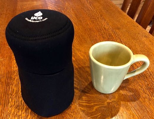
The neoprene cocoon protects the lantern during transport.  This lantern is about the size of a 1 liter nalgene bottle.

Advantages of paraffin wax as a heat source when voyaging:

  1. Paraffin won’t spill out of the lantern.
  2. Paraffin won’t leak from it’s storage container.
  3. Paraffin stores and transports easily without any special considerations.
  4. Paraffin is virtually odor free.
  5. Paraffin UCO candles last 9 hours.
  6. The 3 candle lantern allows three different heat settings:  High, medium and low.

I just received my UCO Candlelier today via UPS.  I have high hopes that this larger, 3 burner candle lantern will be just the ticket for Hagoth, my Skiff America and my Hilleberg Nammatj 3 man tent.  Based on my experience with the single candle lantern, I think I’m going to love this larger, hotter design.  


More Footwell/Filler Board Details

If you’re getting bored with all these footwell details, I might recommend you go for a jog instead of reading yet another post on the the footwell/filler board system.  Otherwise, let’s dive back in to finish up some of the minor yet critical details.

IMG_1974

The above photo shows the 3/4″ side panel notched and ready to receive the beam.

IMG_1970

Above, I’ve pulled the cockpit sole back to reveal the details.  The beam is made from oak and drops into the side panel notch to span across the footwell.  It measures 1,1/4″ x 1,7/8″ x approx. 28,1/2″.   I rounded all exposed corners for safety and comfort.

IMG_1969

The above photo shows the oak beam with the cockpit sole properly positioned.  The beam sits fore of the cockpit sole to form a cleat  (5/8″) to support the footwell grate that will hang from it. I’ll place another cleat on the opposite side of the footwell to match.

IMG_1972

Notice the footwell cleat along the seat longitudinal.  This will serve to narrow up the footwell to properly fit the grate.  Why?  Well, remember, the grate is serving 3 distinct purposes on Hagoth:  1-to keep my cold wet feet up off the bottom of the footwell, out of the water, sand and grit, 2-to flush up the footwell when sleeping solo, and 3-to serve as a large filler board up top when sleeping 2 aboard.  Hence, it needs to fit properly in all 3 of these locations.  The new Mark II kit extends the seat tops by 1″ on each side, hence the need to narrow up the floor of the footwell so the grate will fit in both locations.  The top of this cleat will sit flush with the top of the grate, so it doesn’t take out room from the footwell, but instead reduces flood-able area while keeping the top edge of the cleat flush with the top edge of the grate.

IMG_1971

Finally, I beefed up the bottom cleat that retains the filler boards, it now measures 1,1/4″ x 5/8″ x 18″.

Up Next:  I’ll epoxy all the part and then begin installing them into the footwell.  


Mocking Up Footwell/Filler Board System

I mocked up the footwell/filler board system this evening to see if it’ll work.  I think with a little more fiddling, I’ll have it.

IMG_1967
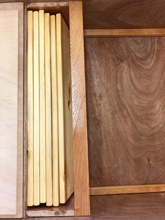
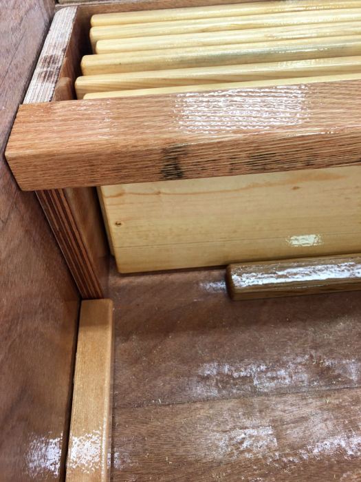
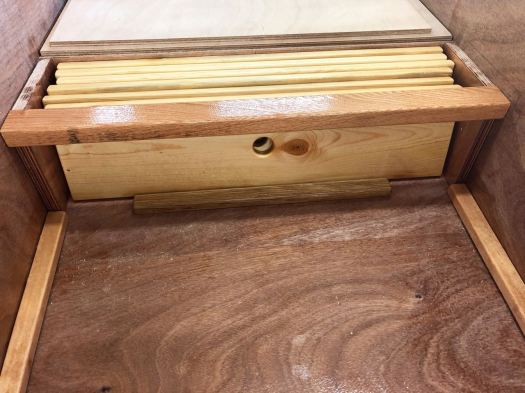
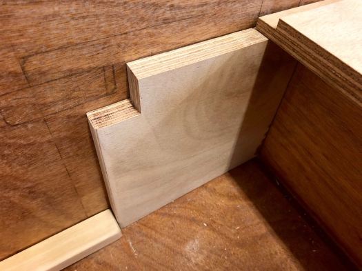
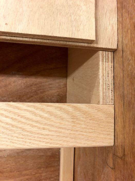
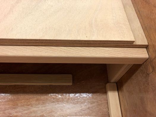
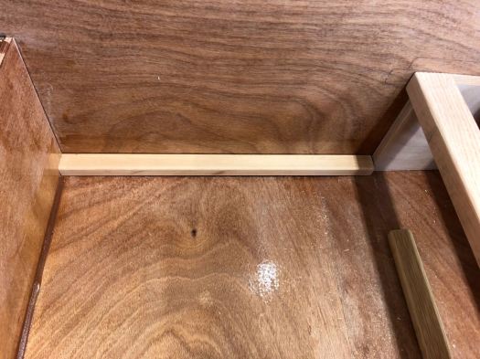
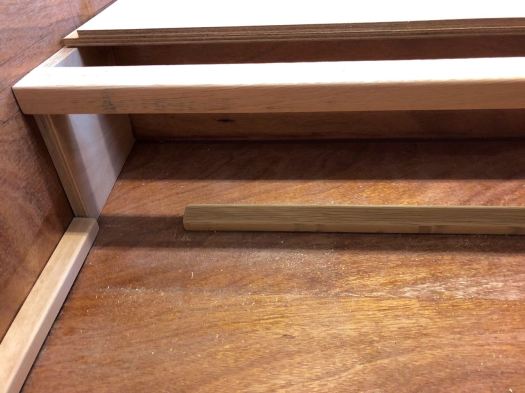
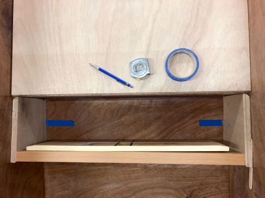
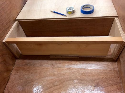
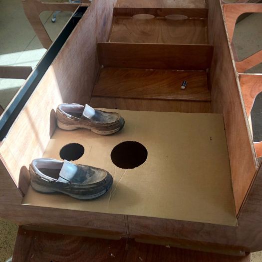
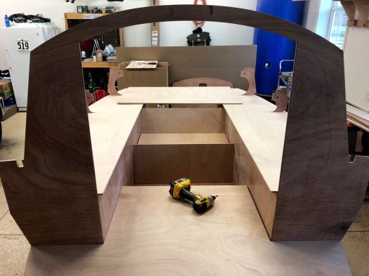
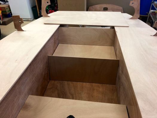
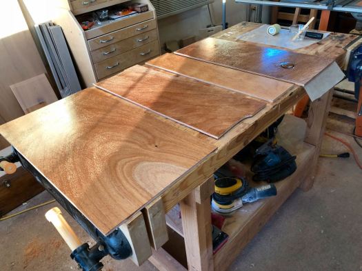
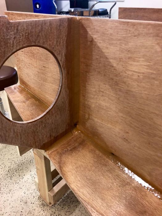
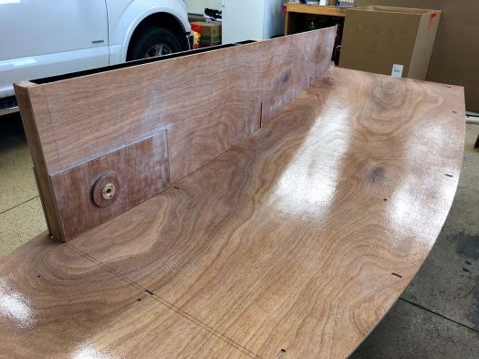
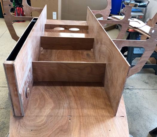
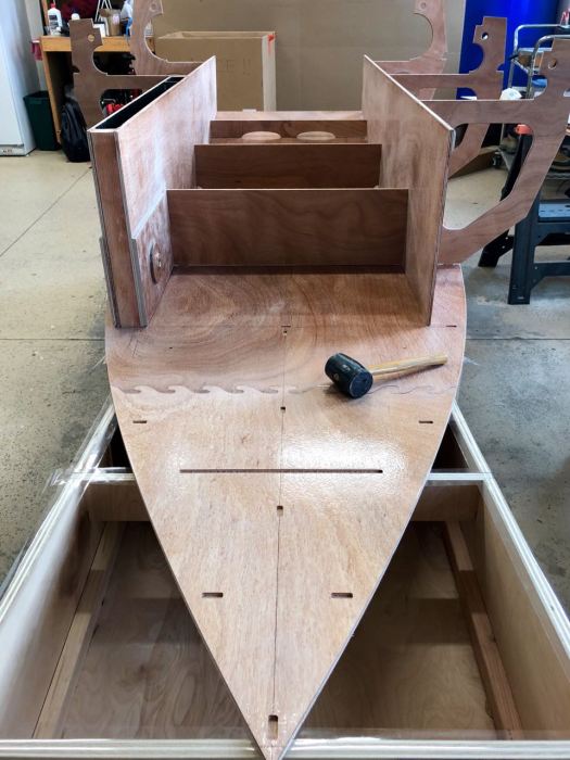
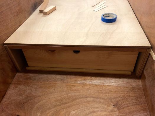
This is roughly how the finished product will appear (with less gap on the sides).  This is an 18.5″ footwell, but along the aft edge, you see filler boards.  The bottom 1/2″ cleat keeps the boards from spilling forward.  The top cleat stiffens the cockpit sole and provides a stop for the filler boards to rest against.

IMG_1964

If I pull the cockpit sole aft, it reveals a top view.  See how the last filler board will rest against the beam.  This keeps them from spilling into the footwell.  The blue tape represents the space taken up by the additional 5 filler boards.

IMG_1965

If you lift the filler board up, the bottom edge of the board clears the bottom cleat and out it comes.  Simple, effective and requires no moving parts.

Additional design thoughts: I plan to fit the beam into the side plates for additional strength.   I’ll also build the beam with a fore cleat protruding into the footwell to support a grate designed to bridge across the footwell.  This same grate will reside on the bottom of the footwell when stored.  Lots more to discuss, but it’ll be much easier to explain as I build it, so stay tuned.

Footwell and Ballast Doublers

After applying 2 coats of epoxy to all the parts, I was ready to install the doublers into both the footwell and the ballast tank.  These areas will both receive 2 additional coats of epoxy before being finished.

IMG_1963

Steps I followed:

  1. wet rolled all mating surfaces using a foam roller and epoxy.
  2. mixed up several batches of thickened epoxy and globed onto the bottom of all the doublers.
  3. used a trowel with an 1/8″ tooth to evenly distribute the thickened epoxy across the bottom of all the doublers.
  4. ran a fillet around all inside edges of the areas of the ballast tank and footwell.
  5. dropped the panels into position.
  6. placed bricks on the panels to weight them properly.

After a few hours of cure time, I’ll come back, remove the bricks and then add another final fillet on top of the panels.  It’s much easier to work the fillets when the brick are out of the way.

Up Next:  Final filleting of the water ballast tank–lots more design work for the footwell.

More Design Thoughts and Details

I will attempt to explain a few more details regarding the footwell/filler board system.  You already know the problem:  Where to store all the filler boards used to create a sleeping platform for 2 aboard Scamp?  Here’s at least one idea.

IMG_1961
Instead of adding another bulkhead to seal off the aft portion of the footwell, leave it open.  But wait, you say “what about all that increased flood-able area?”  How about we fill the area with filler boards?

The above photo represents an 18.5″ footwell.  But, you’ll notice the cockpit sole is cantilevered out over B#6.  In short, I plan to store the filler boards underneath this area.  Leaning the filler boards up vertically against B#6 and storing forward, you can easily store 6-7 filler boards of 7/8″-1″ widths.  This thickness of filler boards should be strong enough to span the roughly 26.5″ distance across the seats.  There will be a few more subtleties.  I’ll place a beam (running side to side) under the edge of the cockpit sole to stiffen the cockpit sole, and add a cleat on the bottom of the floor to act as a keeper to prevent the boards from spilling out into the footwell.  In this way, the boards have a nice tidy home, out of the way while they also reduce the flood-able area of the enlarged footwell.  More details to follow…

I’m also reconsidering the location of the ballast tank hatch.

IMG_1959
My earlier thought was to go 6″ on center.  But I’m now leaning towards 4″ near the edge.  

Upon further review, I’m opting for a smaller hatch located up against the seat longitudinal.  Why?  Well, look at the location of the shoes in the above photo.  A smaller hatch nests nicely between ones legs, while leaving the center isle free from hatches.  I don’t want to be standing on the hatch each time I step my mast.  I also don’t want to be sitting on the hatch when seated in my Crazy Creek chair looking aft, with my feet in the footwell.  OK, but why smaller?  With 4-5 coats of epoxy in the water ballast tank, I’m not sure I’ll ever need to refinish this area.  And, a smaller hatch is easier to seal. Remember, you’ll be sailing on an angle hence there will be a lot of water pressure (from the back side) on this hatch.  But what about the storage for cold drinks?  The storage between B#3-B#4 will have to be cold enough for the drinks.  In the end, I feel better about a small screw down hatch for this area. 

IMG_1960

With the above thoughts in mind, I’m electing to place the drain plug in the more traditional location, centered within the bulkhead (remember, one foot on each side), just off the longitudinal, directly below the intended hatch location.

IMG_1957
This is a 78″ x 3.25″ x 25″ wide Big Agnes air mattress.  Notice how nicely the 25″ wide mattress fits into this area.  You head and shoulders can fit nicely under the veranda, while your legs extend down the isle.  Nice design work John Welsford.

How far back can I place the front edge of the lazarette?  I let the Big Agnes dictate this number, plus 1″ as a safety margin.  Even though the mattress labels itself as 78″ long, the tape measure reveals the inflated mattress to be 76″ long.  My sleep-able area will be build exactly 77″ long.

IMG_1958
The front face of the lazarette will taper 1.5″ aft at the top edge.  

Why are you getting so far ahead of yourself?

Why not just continue with the next step and address these issues at a later time?

 I like to consider all these issues now, while the access into the boat is very unrestricted and open.  Things get much tighter and harder to reach during the later stages.  Also, I’ve found if I don’t work several step ahead of myself, I get caught later when issues become much harder to fix.  

Footwell and Ballast Tank Design

I’m always trying to simplify and improve this most excellent design and kit.  Given my particular needs, I have a few design chances in store for the footwell.  I’m working on a design that will store the filler boards under the aft section of the footwell.  These boards are awkward to store and take up a lot of space, that’s always an issue on a small boat.  In thinking through the options, under the aft end of the footwell seems to make good sense.  Hence, I will lean the filler boards up against and on the front side of the  existing bulkhead #6.  By the time you store 6 filler boards, the remaining footwell will be approximately 19.5″ wide.  I’ll hang the cockpit sole over this area (and place a beam underneath it for strength).  The footwell will look small and efficient, but the aft end will be taken up by  filler board.

IMG_1949
Trying to visualizing the footwell, veranda, lazarette and the seat tops. 
IMG_1952
If sleeping alone on the boat, I will be sleeping on the cockpit sole.  My head will be tucked under the veranda, with my feet aft.  Im 6′ tall and need about 6’5″ to sleep comfortably.  Hence, I’ll need 6’5″ between bk#3 and the front face of the lazarette.  This measurement governs where I place the front face of the lazarette.  Once that measurement is set, you can measure the horizontal distance between the front face of the lazarette and the aft end of the footwell.  This distance needs to be a comfortable distance to sit on when you lean back against the lazarette, facing forward and place your feet in the footwell.  By making the footwell 19.5″ wide (fore to aft), it leaves me with a comfortable 18″-19″ of horizontal surface to sit.  A narrower footwell forces a deeper seat, which is less comfortable for me.  My point in all this hyperbole is to emphasize how important it is that you make the boat work for you.  
IMG_1953
My current thought on the lazarette is to place a large opening on the top panel, with no hatch cover – that’s right, just a large opening along the center line.  A large open area to jam wet anchor line, a dry (wet) suit, fenders or any other quick storage item. I really love a tidy cockpit, the open top lazarette will allow me to throw all sorts of stuff in through the top and get it quickly out of my way.  I plan to create a drainage hole on the forward face of the lazarette for air flow and drainage.  Water in the lazarette (from rain) will make it’s way to the footwell, where I’ll bucket the collection of water out of the boat.  
IMG_1954
Where to install the ballast tank hatch?  Many locate this hatch near the center board pivot bolt.  After mocking up a few different locations, I’m leaning toward a 6.75″ opening (Armstrong 6″ hatch) centered over the ballast tank.  Even with the hatch centered, I’m easily able to reach the drain plug and the center board plug/pin.  And, it’s easier to reach all the real estate when drying the inside after each sail and to retrieve your cold drinks that you place in the ballast tank to keep cool.  The center location will also make it easier to refinish the inside when needed.  
IMG_1955
First coat of epoxy on the ballast tank and footwell doublers.  
IMG_1956
And, if you drill the drain hole in the wrong location, you can epoxy it back into position and try again.  

There’s so much to think about, design and consider in this phase.  Much credit goes to my dad for his excellent thoughts on the design changes I’ll be implementing into Hagoth.  This is one of the most exciting aspects of building your own boat.

Up Next:  More footwell design, explanation and work.  

Filleting Bulkheads 4-6

Yesterday I got some late night filleting accomplished.  My wife says she’s now a boat widow until Hagoth is finished.  Mix that with viewing college football and things get a little tight around here.

Check it out:

IMG_1941
Before filleting, I used the seat top to the help hold the bulkheads in their proper alignment.  I then went underneath and marked this alignment.  I then nailed a small nail through the longitudinal into the bulkhead to hold it into it’s proper location.  

IMG_1943IMG_1944IMG_1947

IMG_1948
Make sure you’re leaving room for the stem and garboard plank.  

I used a sharpened craft stick to remove all excess epoxy.  The clean up takes longer than the filleting, but it’s worth every second.  Clean now means much less work tomorrow.

Before I move on to bulkheads 1-3, I want to get the footwell and ballast tank finished.  There’s much better access prior to installing the fore bulkheads.  The Mark II kit comes with the aft footwell bulkhead.  It also comes with a doubler for the ballast tank.  I will however, need to add my own doubler for the floor of the footwell.

Up Next:  Footwell thoughts and design.

Pivot Bolt Details

I promised more details regarding the pivot bolt.

Here they are:

IMG_1933
Modified drain plug with water tight plug inserted – in the go position.
IMG_1934
Plug removed, showing threaded 1/4″ center bolt.
IMG_1936
Stainless wing nut threaded onto the center bolt.  Notice how the wing nut is making contact with the inner edges of the drain housing.  As you continue threading the nut onto the center bolt, it begins extracting the pivot bolt.
IMG_1937
In this position, there’s plenty of surface area to grab the wing nut and the fully extract the pivot bolt.
IMG_1938
Extracting the pivot bolt.
IMG_1939
All the separate parts of the system.

What’s to love:

  1. Once set up correctly, the system is uber simple.
  2. The parts (at least the drain plug) are interchangeable with the water ballast drain system.
  3. There are no screws in the housing or doubler, minimizing water intrusion.
  4. The system traps no water between the housing and the doubler.
  5. Since the system traps no water, there’s nothing to expand and break during a hard freeze (remember, I live in Idaho).

Niggles to manage:

  1. You need to have the standard drain plug cap modified to accept the 1/8″ center bolt.
  2. You need to buy a 6″ stainless pivot bolt to make room for all the mods. (which you will cut to exact size once installed)
  3. You need to have the pivot bolt drilled and taped to accept the 1/4″ center bolt.
  4. You need to mock up all the parts carefully to make sure your plug cap doesn’t contact the center bolt and apply pressure to the outboard side of the retaining cap.
  5. You need to thread and epoxy the center bolt into the pivot bolt at a proper depth to fully accept the wing nut (for extraction) yet not make contact with the plug cap (when tightening the plug cap into the housing).

I realize it’s a little hard to conceptualize all these issues.  Hopefully this all makes sense.  If not, post a question and I’ll try to answer.

I didn’t invent this system.  Eric from Kansas developed the concept.  It was love at first sight to my eyes.  Thanks Eric!!

Going 3D

This morning I had the chance to dry assemble a few of the parts onto the hull.

Check it out:

IMG_1927IMG_1928IMG_1929IMG_1930IMG_1931

It’s sure great to see the boat go 3D within a couple of minutes.  But, now I’ve got a lot to think about as I transition from bench to boat.  Things like:  footwell, how to cleat the footwell and associated filler board, access and storage, ballast tank drainage, doublers for footwell and ballast tank and design work around for a lazarette.  I’m definitely entering an exciting part of the build.

First order of business will probably be the footwell.